![]()
![]()
![]()
![]()
Contact: Dr.-Ing. Maximilian Paßmann, Artem Tukalov
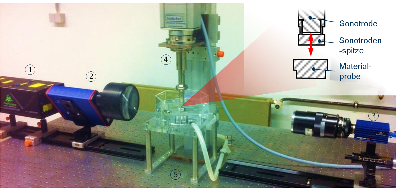
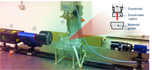
At the sonotrode test stand of the chair (see Fig 1), cavitation erosion measurements according to ASTM G32 are carried out to assess the influence of various fluid properties of technically relevant mixtures on cavitation and cavitation erosion. For this purpose, a closed test stand setup with an integrated fluid circuit has been designed, allowing adjustment of gas content, temperature level, and pressure.
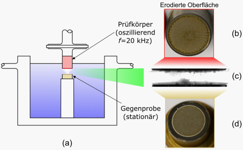
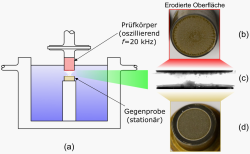
In a sonotrode, cavitation bubbles are generated by the oscillating motion of an actuator (see also Fig 2a). The excitation occurs at about 20 kHz, so-called acoustic cavitation. In the gap between the actuator and the counter-sample, complex bubble clouds are formed, in which the individual bubbles vibrate, merge with each other, and eventually collapse individually or in larger clouds. During implosion, very high pressures occur momentarily, which erode the counter-sample (see also Fig 2b-d). The mechanism of material removal is very complex, as microscopic effects such as the local microstructure have an influence on the material response. At the sonotrode test stand, material removal rates are measured or optical examinations of the bubble structures are carried out. Parameters of the erosion rate include, for example, the fluid (especially bubble nucleation content, e.g., dissolved gas bubbles, and vapor pressure), the material of the counter-sample itself (material properties, especially fracture strength), and environmental factors such as temperature and ambient pressure.
Schreiner, F., Paepenmöller S. & Skoda, R. (2020). 3D flow simulations and pressure measurements for the evaluation of cavitation dynamics and flow aggressiveness in ultrasonic erosion devices with varying gap widths. Ultrasonics Sonochemistry, 67, 105091. DOI: 10.1016/j.ultsonch.2020.105091
Paepenmöller, S.A., Kuhlmann, J., Blume, M. & Skoda, R. (2018). Assessment of flow aggressiveness at an ultrasonic horn cavitation erosion test device by PVDF pressure measurements and 3D flow simulations. Proceedings of the 10th International Symposium on Cavitation (CAV2018), J. Katz (editor). ASME, New York, 6 pp. DOI: 10.1115/1.861851_ch23
Copyright © HSM 2024
Letzte Änderung: 20. Jun. 2024
 pulsed laser, (2) diffuser, (3) double image camera, (4) sonotrode, (5) optical table.")
, eroded surfaces of the oscillating test body and the stationary test specimen (b, d), and transmitted light image of the gap (c).")