![]()
![]()
![]()
![]()
Contact: Dr.-Ing. Maximilian Paßmann, Artem Tukalov
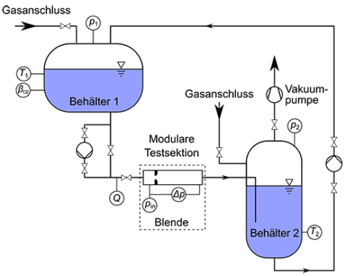
The test stand is used to investigate cavitation phenomena, particularly the influence of dissolved gas content on flow cavitation. The test stand can be operated over a wide range of Reynolds numbers and is equipped with a variable measuring section totaling 1.5 m. Other parameters that can be varied include, in addition to the geometry of the measuring section, roughness, inlet and outlet pressure, dissolved air content of the inflow (via pressure and temperature of the saturation vessel and bypass line), free air content (via air ingress), and pressure and temperature levels before the measuring section.
The cavitation test stand (see Figure 1) is intended for studying the effect of air on flow cavitation. In a reservoir (Container 1), water saturation with a gas (synthetic air) can be achieved via a gas connection. This is done under pressure control and by circulating the water through a bypass line. The second container (Container 2) is used to collect the liquid. In this container, a vacuum can also be generated using a vacuum pump. Lowering the pressure increases the pressure difference across the measuring section and achieves degassing by altering the water's equilibrium solubility. The measuring section is located in a pipeline between the two containers. The pressure difference between the containers causes flow. The modular design of the measuring section allows for the installation of orifices and nozzle geometries. To achieve fully developed flow even at low Reynolds numbers, an inlet section (approx. 4 m) before the measuring section is required. The experiments are conducted in batch mode to avoid altering the conditioned water in the first container.
Limbach, P., Kowalski, K., Hussong, J. & Skoda, R. (2018). Numerical simulation of cloud cavitation in hydrofoil and orifice flows with analysis of viscous and non-viscous separation. ASME. J. Fluids Eng. 2018, 140(11):111102-111102-13. DOI: 10.1115/1.4040069
Kowalski K., Pollak S., Skoda R. & Hussong J. (2018). Experimental Study on Cavitation-Induced Air Release in Orifice Flows. ASME. J. Fluids Eng. 2018, 140(6):061201-061201-7. DOI: 10.1115/1.4038730
Copyright © HSM 2024
Letzte Änderung: 20. Jun. 2024

